Half wave rectifier circuit diagram Full wave bridge rectifier download scientific diagram Single phase full wave rectifier circuit diagram
3 Phase Bridge Rectifier Circuit Diagram
Rectifier tapped circuit operation circuitglobe
8: three-phase full-wave bridge rectifier circuit
Bridge rectifier schematic diagram3 phase bridge rectifier circuit diagram Rectifier wave bridge full circuit diagram diode voltage operation fig its shown below inverse peak disadvantages value when negativeCircuit diagram of full rectifier.
The single phase bridge full wave rectifier download scientific diagram[diagram] h bridge circuit diagram Center tapped full wave rectifierThree phase full wave bridge rectifier circuit diagram pcb designs.

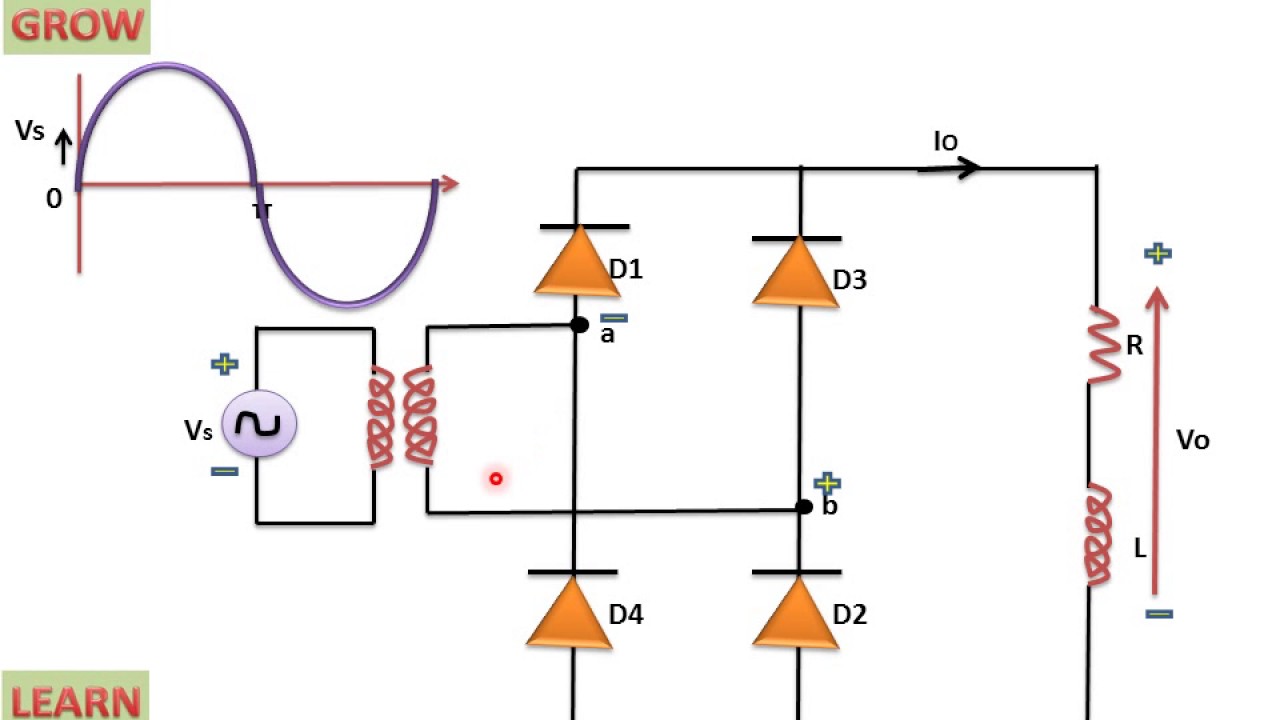
What is single phase full wave controlled rectifier? working, circuit
Full wave bridge rectifier – circuit diagram and working principleHalf wave bridge rectifier circuit diagram Full-wave bridge rectifier circuitFull wave bridge rectifier operation.
Rectifier operation diode diodes biased d1 กระแส engineeringtutorialHalf wave full wave and bridge rectifier diagram What is single phase full wave controlled rectifier? working, circuitThree phase full wave bridge rectifier circuit diagram pcb designs.
What is single phase full wave controlled rectifier? working, circuit
Rectifier capacitor resistor transcription electricalFull wave bridge rectifier What is single phase full wave controlled rectifier? working, circuitHalf wave bridge rectifier circuit diagram.
.


